Schema-Driven, Framework-Agnostic Forms: Building a Runtime Engine for React, Vue, Angular & Vanilla JS

In this article, I explain how to build dynamic, schema-driven forms that work across React, Vue, Angular, and Vanilla JS using a registry-driven runtime engine. The forms fully decouple data, UI, and logic, and support conditional logic, dynamic validation, and plugin extensibility—all without hardcoding components.

In most form systems, even schema-driven ones, logic is still tightly coupled to structure or UI.

The goal of Formitiva is to go further:

Fully decouple data, presentation, and behavior

The Problem with Traditional Separation

Typical systems separate:

  • data (JSON schema)
  • UI (components)

But logic often remains:

  • embedded in schema
  • hardcoded in components
  • tied to specific frameworks

This creates hidden coupling.

The Key Idea: Reference, Don’t Embed

Instead of embedding logic:

{
  "field": "email",
  "validatorHandlerName": "emailValidator"
}

The schema only references behavior.

It does not define:

  • how validation works
  • how UI renders
  • how logic executes

The Registry System

All implementations live in a registry:

  • component registry
  • validation registry
  • logic/workflow registry

The registry acts as a lookup system:

string reference → actual implementation

The Runtime Engine

The runtime engine is responsible for:

  • Parsing schema
  • Resolving references via registry
  • Executing logic (validation, conditions)
  • Delegating rendering

This transforms the system into:

Schema → References → Registry → Runtime Execution

Renderer Abstraction (Framework-Agnostic Design)

The runtime does not render UI directly.

Instead, it delegates to renderer adapters:

  • React
  • Angular
  • Vue
  • Vanilla JS

Each adapter:

  • receives abstract UI definitions
  • maps them to framework-specific components

The Resulting Architecture

You get a layered system:

  • Schema → declarative intent
  • Registry → implementation mapping
  • Runtime → execution engine
  • Renderer → UI layer

Extensibility Through Plugins

Because everything is resolved via registry:

  • new components can be added
  • new validators can be injected
  • new behaviors can be introduced

Without modifying core logic.

Why This Matters

This architecture enables:

  • true separation of concerns
  • cross-framework portability
  • backend-driven UI
  • low-code possibilities
  • long-term scalability

Final Thought

Decoupling isn’t just about separating files or layers.

It’s about removing direct knowledge between parts of the system.

The registry pattern achieves that by introducing controlled indirection at runtime.

That’s what makes Formitiva fundamentally different.

Tamagrow: Automatic Content Creation For Devs

There’s a specific frustration that only builders understand.

You’re deep in a codebase. You just refactored the auth flow, fixed three edge cases, and deployed a feature that changes how the whole thing works. You close your laptop, feel good for about ten minutes, and then realize nobody saw any of it.

Not your followers. Not the people who’d actually use the thing. Not the recruiter who looked at your GitHub once and moved on because there was no narrative attached to the green squares.

That was me for months. Shipping consistently, building things I was proud of, and watching people with half the output get ten times the visibility because they wrote a LinkedIn post about it.

I didn’t have a posting problem. I had a friction problem.

The gap isn’t motivation. It’s timing.

Right after I push a meaningful commit, there’s a five-minute window where I could articulate exactly what I built and why it matters. The context is loaded. The excitement is there.

But I never write the post in that window. I’m already onto the next thing, or I tell myself I’ll do it later and “later” turns into “never.”

By the time I sit down to write, I’m staring at a commit history trying to reverse-engineer what I was thinking three days ago. So I don’t post. Again.

What if something caught that moment for me?

Building the thing I kept wishing existed

That question turned into Tamagrow. I started building it with two teammates, we’ll call them A and N, with a simple premise: what if your work spoke for itself, automatically?

Connect your GitHub repo or an RSS feed, and Tamagrow watches for updates. When you push something significant, it drafts a post tailored for LinkedIn, X, or wherever your audience lives. You get an email, review the draft, and approve with one click. The whole loop takes about ten seconds.

No context switching. No staring at a blank LinkedIn editor at 11 PM trying to sound professional about a commit you made at 2 AM.

The moment it clicked

We’d been showing Tamagrow at hackathons and campus events, getting solid reactions but nothing that made me think okay, this actually works. Then my partner A demo’d it at Startup Village talks at a pitch event.

Mid-presentation, a guest speaker in the audience pulled out their laptop, connected their own repo, pushed a commit, and watched a draft appear in real time. Unprompted. On their own code.

They didn’t ask permission. They just wanted to see if it was real.

That was the moment I stopped thinking of Tamagrow as a side project and started thinking of it as a product.

What Tamagrow actually does

For the builders who skipped the story (no judgment):

  • Connect your sources. GitHub repos for commit monitoring, RSS feeds for blog/article tracking. Same pipeline.
  • Significance rating. Not every commit deserves a post. Tamagrow rates updates 1–5 and only drafts the ones worth talking about.
  • Platform-tailored drafts. Tuned for LinkedIn, X, and more. Different norms, different formats, same story.
  • One-click approval. Review from your dashboard or directly from email. Nothing publishes without your say-so.
  • Tone and voice controls. Set a voice per account so posts sound like you, not a bot.

Your work deserves an audience. Tamagrow makes sure it gets one.

Who this is for

We built this for the version of me who was pushing code every day and had nothing to show for it publicly. Turns out that problem is everywhere:

Solo devs and indie hackers who want to build in public but can’t stop building to write about building.

Job seekers and students doing the work but not getting credit. Your GitHub activity is impressive. Most hiring managers just never see it.

Technical writers who publish tutorials but forget to promote them. Connect your RSS feed and let Tamagrow handle distribution.

What’s next

Tamagrow is live at tamagrow.app. Free to start, no credit card required.

We’re early. The product works, the core loop is solid, and we’re shipping improvements based on real feedback. If you try it and something feels off, or something clicks, I want to hear about it.

I’m building this in public too (with Tamagrow’s help, obviously). Follow along here on dev.to, or come say hi in the comments.

If you’ve ever closed your laptop after a great session and thought I should really post about that and then didn’t, this is for you.

Solving the Noisy Neighbor Problem: A Multi-Year Journey to IO Isolation on Kubernetes

Section 1: Introduction

Why I’m Writing This

This is the story of a multi-year effort to solve a large-scale data company’s noisy neighbor problem on Kubernetes—a fundamental limitation that blocked the migration of critical stateful workloads to our platform.

By the end of my tenure, we had validated a solution through a partnership with Intel. The test cluster proved the approach worked, four cross-functional stakeholders approved the design, and a clear rollback strategy ensured operational safety.

I’m writing this blog to preserve the knowledge, recognize the collaborative effort, and help others facing similar challenges. Multi-year infrastructure transformations are hard. The biggest challenges aren’t always technical—they’re about identifying the right problem, convincing people the solution is necessary, and getting teams to work together. This writeup documents what we learned so the effort doesn’t get lost.

The Context: A Platform Under Pressure

The company’s Kubernetes platform isn’t just running stateless web applications—it’s the engine for massive, stateful data systems. At this scale, vanilla Kubernetes starts to break down. We maintained our own internal fork with some custom patches to survive our operational requirements.

Solving the noisy neighbor problem required a multi-year transformation:

  1. Phase 1: The Foundation – Upgrade Kubernetes from v1.18 to v1.22 to enable cgroup v2 support (required for IO throttling)
  2. Phase 2: The Solution – Integrate IOIsolation to provide IO-aware scheduling and preventive isolation

This is the story of that journey.

Section 2: The Problem – Kubernetes is IO-Unaware

The Fundamental Gap

Kubernetes scheduling has a fundamental limitation: it’s IO-unaware. The scheduler considers CPU and memory when placing pods, but completely ignores IO capacity:

  • No visibility into node IO bandwidth (disk or network)
  • No way for pods to request IO resources
  • No mechanism to prevent multiple high-IO workloads from landing on the same node

This isn’t a bug—it’s a design gap. Kubernetes assumes IO resources are either infinite or managed externally. For many workloads, this assumption is fine. Given our large scale and workload mix, it was a critical problem.

The Symptoms

The IO-unaware scheduling led to recurring production incidents:

  1. Multiple IO-hungry pods would be scheduled on the same node (no IO capacity awareness)
  2. These pods would consume excessive disk or network bandwidth
  3. Kernel CPU would spike due to interrupt handling and context switching
  4. The Docker daemon would hang, unable to respond to requests
  5. Kubelet’s Pod Lifecycle Event Generator (PLEG) would timeout trying to reconcile container state
  6. Nodes would be marked NotReady, triggering cascading alerts and pod evictions

A particularly insidious failure mode: If a high-IO workload caused a kernel-level IO hang, the Docker daemon would often block, triggering a PLEG timeout. This made the Kubelet think the node was dead, even if CPU was at 0%.

Multiple teams were filing incidents. Internal engineering jobs were disrupted. But the most critical impact was strategic: we couldn’t migrate database-like applications to Kubernetes because the noisy neighbor risk was too high.

The Investigation

  • IRQ counts spiking during IO-heavy workload activity
  • Excessive context switching correlating with IO load
  • Docker daemon behavior and recovery patterns

When the Docker daemon hung, restarting it didn’t help. In fact, it often made things worse. When system CPU was high, the new Docker daemon could fail to start. Reactive recovery (restarting Docker) was unreliable.

Testing the Xen Hypothesis

I initially suspected AWS’s Xen hypervisor might be the culprit. On older instance types (m4, c4, r4), Xen’s dom0 handles disk I/O virtualization in software, which can cause severe CPU steal time during high I/O operations.

So I tested the same workloads on Nitro instances (c5, r5), which offload EBS I/O and network virtualization to dedicated hardware cards. There’s no dom0 stealing CPU cycles.

The same failure occurred on Nitro. This confirmed what I expected: hardware offloading cannot fix OS-level kernel bottlenecks. Even with Nitro’s hardware acceleration, the kernel still processes I/O interrupts, context switches, and completion handlers. When noisy neighbors saturated I/O, kernel CPU spiked, and the Docker daemon couldn’t recover.

The IO-Blindness Trap

  • The Scheduler Issue: Standard K8s is “IO-Unaware.” It treats a node with 10 pods and a node with 50 pods as equally “available” if the CPU/Mem metrics are the same, completely ignoring the IOPS/Throughput saturation on the underlying EBS/Disk.
  • The Stack Issue (Dockershim): High IO workloads don’t just slow down neighbors; they saturate the Docker daemon. Because Dockershim/Docker is a centralized bottleneck, a single pod’s IO burst can cause the daemon to hang, leading to a NodeNotReady state.
  • The cgroup v1 Limitation: You can’t fix this with software tweaks because cgroup v1 cannot track or throttle buffered IO (writes that go to the page cache first).

Why Containerd Helps (But Isn’t Enough)

Moving to containerd (standard in Kubernetes v1.22+) removes Dockershim and the heavy Docker daemon. Containerd is a “lean” runtime—significantly more resilient to being locked up by a single pod’s behavior. This improves node stability.

But even with containerd, the underlying Linux kernel still has the same limitation under cgroups v1. Containerd makes the management layer (the runtime) more stable, but it does nothing to protect the data layer (the performance of neighboring pods).

Containerd reduces the risk of node-level failures, but doesn’t solve the noisy neighbor problem.

The Solution Requirements

Solving this required two things:

  1. IO-aware scheduling: Place pods based on available IO capacity (scheduler plugin)
  2. Preventive isolation: Throttle buffered I/O before it saturates the kernel (cgroups v2)

Section 3: The Foundation – Preparing the Platform

IOIsolation had strict technical prerequisites that required significant preparation work:

1. Kubernetes v1.22 Minimum

IOIsolation required Kubernetes v1.22 or higher with systemd as the cgroup driver.

2. Custom AMI with cgroup v2 Enabled

We built a custom Amazon Machine Image (AMI) with the OS kernel configured to enable cgroup v2 by default. This required:

  • Setting kernel boot parameters to enable cgroup v2
  • Validating compatibility with existing workloads

3. Dual Filesystem Compatibility

Another requirement was ensuring the IOIsolation code worked with both cgroup v1 and v2 filesystems. Why?

  • We couldn’t flip the entire fleet to cgroup v2 overnight
  • Different node pools might be at different migration stages
  • Rollback scenarios required v1 compatibility

Section 4: The Solution – IO Isolation Architecture

Part A: System Overview

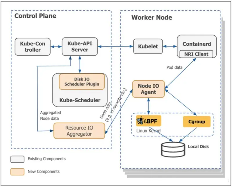
IOIsolation provides IO-aware scheduling and enforcement through cgroup v2. The system consists of four main components working together to ensure pods get the IO bandwidth they need while preventing noisy neighbors from impacting others.

Figure 1: High-level design of the IOIsolation framework. The system integrates a custom Kubernetes Scheduler Plugin with a node-level Enforcement Agent to solve the “noisy neighbor” problem. It utilizes CRDs for state management, cgroup v2 for throttling, and a specialized Aggregator to maintain scalability across thousands of nodes.

The Four Components:

  1. Scheduler Plugin – Makes IO-aware pod placement decisions
  2. Node Agent – Monitors IO usage and enforces limits via cgroups
  3. Custom Resource Definitions (CRDs) – Configuration and state management
  4. Aggregator (optional) – Centralized monitoring and coordination

As shown in Figure 1, the Control Plane contains the Disk IO Scheduler Plugin and Resource IO Aggregator, while each Worker Node runs the Node IO Agent (which handles eBPF monitoring, cgroup enforcement, and NRI integration). The CRDs (NodeStaticIOInfo, NodeIOStatus) flow between these layers to maintain consistent state.

Let’s examine each component and how they work together.

Component 1: Scheduler Plugin

The scheduler plugin extends Kubernetes’ default scheduler with IO awareness. When a pod requests IO resources, the scheduler ensures it’s placed on a node with sufficient available bandwidth.

How It Works:

1. Pod Creation

apiVersion: v1
kind: Pod
metadata:
  annotations:
    ioi.intel.com/disk-bandwidth: "100MB/s read, 50MB/s write"
    ioi.intel.com/network-bandwidth: "200Mbps"

2. Scheduler Plugin Reads Annotations

  • Parses IO requirements from pod annotations
  • Determines IO class (GA = Guaranteed Allocation, BE = Best Effort)

3. Filter Phase

  • Eliminates nodes without sufficient IO capacity
  • Checks NodeIOStatus CRD for each node’s available bandwidth

4. Score Phase (LeastAllocated Strategy)

  • Ranks remaining nodes by available IO capacity
  • The LeastAllocated strategy acts as a natural dampener, spreading the pods out and preventing a “thundering herd” from piling onto a single node before the CRDs can update.

5. Bind Phase

  • Assigns pod to selected node
  • Updates node’s reserved bandwidth

The Scheduler’s View of Node Capacity:

The scheduler maintains a local cache of node IO capacity by watching NodeIOStatus CRDs:

// Simplified example
type NodeIOStatus struct {
    NodeName string
    DisksStatus map[string]DiskStatus {
        "/dev/sda": {
            GA: {  // Guaranteed Allocation pool
                In:  500,  // 500 MB/s read available
                Out: 400,  // 400 MB/s write available
            },
            BE: {  // Best Effort pool
                In:  100,  // 100 MB/s read available
                Out: 80,   // 80 MB/s write available
            }
        }
    }
    NetworkStatus: {
        GA: { In: 800, Out: 800 },  // 800 Mbps available
        BE: { In: 100, Out: 100 },  // 100 Mbps available
    }
}

The scheduler reads node capacity from CRDs via standard Kubernetes Informers (watch mechanism).

Component 2: Node Agent

The node agent is the “brain” of the system, running as a DaemonSet on each node. It works with ioi-service to monitor and enforce IO limits.

Note: In Figure 1, the “Node IO Agent” box represents the combination of two components working together: the Node Agent (running as a Kubernetes DaemonSet) and the ioi-service (running as a systemd service with root privileges). This separation allows the DaemonSet to handle Kubernetes integration while the privileged systemd service performs low-level cgroup operations.

The ioi-service runs as a privileged system service (runs via systemd) that handles the low-level IO monitoring and enforcement:

  • Monitors IO via eBPF or io.stat (cgroup v2)
  • Writes bandwidth limits to cgroup files
  • Communicates with node-agent via gRPC over Unix socket

The node agent has three main responsibilities:

1. Bandwidth Profiling (Disk Only)

When the node-agent starts, it measures actual disk bandwidth capacity using fio (Flexible IO Tester):

# Example: Test 4K random read on /dev/sda
fio --filename=/mnt/sda/test 
    --direct=1 
    --rw=randread 
    --bs=4k 
    --size=20G 
    --runtime=60s 
    --output=results.json

The agent tests multiple block sizes (512B, 1K, 4K, 8K, 16K, 32K) for both read and write operations. Results are stored and reused (profiling takes ~10 minutes per disk).

Network bandwidth is simpler: The agent reads the link speed from sysfs (/sys/class/net/eth0/speed) or uses a configured value.

2. Pool Management

The agent divides bandwidth into pools based on admin configuration:

# Admin ConfigMap
diskpools: |
  ga=100   # Guaranteed Allocation: 100% of capacity
  be=20    # Best Effort: 20% of capacity

networkpools: |
  ga=95    # Guaranteed Allocation: 95% of capacity (950 Mbps)
  be=5     # Best Effort: 5% of capacity (50 Mbps)

Example calculation:

Disk Capacity (from profiling): 650 MB/s read, 600 MB/s write
↓
GA Pool:  650 MB/s × 100% = 650 MB/s read, 600 MB/s write
BE Pool:  650 MB/s × 20%  = 130 MB/s read, 120 MB/s write

3. Dynamic Bandwidth Enforcement

The node-agent continuously monitors actual IO usage and adjusts limits dynamically. It enforces these limits at two distinct layers:

A. Block Layer Enforcement (cgroups)

Every 2-5 seconds:

  1. Receive bandwidth data from ioi-service (via gRPC)
  2. Calculate actual usage per pod, per QoS class
  3. Recalculate available bandwidth
  4. Update cgroup io.max limits via ioi-service

B. Network Layer Enforcement (tc & ifb)

Because cgroups don’t throttle networking, the node agent uses Linux Traffic Control (tc). It creates an Intermediate Functional Block (ifb) device for the pod. This allows us to reliably shape both ingress and egress traffic, ensuring BE pods don’t starve GA pods of network bandwidth.

The system dynamically adjusts BE bandwidth based on actual GA/BE usage. For disk IO, BE can be squeezed to almost nothing. For network IO, each BE pod maintains a minimum bandwidth to prevent TCP connection timeouts.

Component 3: Custom Resource Definitions (CRDs)

The system uses three CRDs to manage configuration and state:

1. NodeStaticIOInfo – Static node capacity (from profiling)

apiVersion: ioi.intel.com/v1
kind: NodeStaticIOInfo
metadata:
  name: node1-staticinfo
spec:
  nodeName: node1
  disks:
    - id: "disk-sda"
      path: "/dev/sda"
      capacity:
        read: 650   # MB/s
        write: 600  # MB/s
  network:
    linkSpeed: 1000  # Mbps

2. NodeIOStatus – Dynamic node status (updated frequently)

apiVersion: ioi.intel.com/v1
kind: NodeIOStatus
metadata:
  name: node1-nodeioinfo
status:
  disksStatus:
    disk-sda:
      GA:
        In: 500   # 500 MB/s read available
        Out: 400  # 400 MB/s write available
      BE:
        In: 130   # 130 MB/s read available
        Out: 120  # 120 MB/s write available
  networkStatus:
    GA: { In: 800, Out: 800 }
    BE: { In: 50, Out: 50 }

3. IOIPolicy – IO classes and policies

apiVersion: ioi.intel.com/v1
kind: IOIPolicy
metadata:
  name: default-policy
spec:
  ioClasses:
    - name: "GA"  # Guaranteed Allocation
      priority: 1
    - name: "BE"  # Best Effort
      priority: 2

Component 4: Aggregator (Optional)

The aggregator sits between node-agents and the Kubernetes API server, collecting metrics and batching updates.

Data Flow With Aggregator:

Node-agent (node1) ──┐
Node-agent (node2) ──┤
Node-agent (node3) ──┼──> Aggregator ──> Batch Update ──> NodeIOStatus CRDs
       ...           │
Node-agent (nodeN) ──┘

What it does:

  1. Receives bandwidth metrics from all node-agents via gRPC
  2. Batches updates (every 5 seconds, configurable)
  3. Writes to NodeIOStatus CRDs in Kubernetes API server
  4. Reduces API server write load by ~90% at scale

Data Flow Without Aggregator (Direct Mode):

Node-agent (node1) ──> Write NodeIOStatus CRD ──> API Server
Node-agent (node2) ──> Write NodeIOStatus CRD ──> API Server
Node-agent (node3) ──> Write NodeIOStatus CRD ──> API Server
       ...

Each node-agent writes directly to its own NodeIOStatus CRD.

Complete Workflow

A complete workflow from pod creation to IO enforcement:

  1. Step 1: Pod Submission & Specification
  2. Step 2: Scheduler Plugin Filters Nodes
  3. Step 3: Node-Agent Registers Pod
  4. Step 4: IOI-Service Applies Limits
  5. Step 5: Continuous Monitoring

    • Every 2-5 seconds:
      1. ioi-service reads io.stat
      2. Calculates bandwidth: 180 MB/s read, 95 MB/s write (under limit)
      3. Sends to node-agent via gRPC
      4. Node-agent updates NodeIOStatus CRD (directly or via aggregator)
      5. Scheduler sees updated capacity for future scheduling decisions
  6. Step 6: Dynamic Adjustment

Part B: Design Trade-offs: Flexibility and Robustness

While integrating IOIsolation, we faced several architectural decisions. Rather than viewing these as binary choices, the ideal approach is to implement both options and let administrators choose based on their specific context. Here’s how we approached these trade-offs:

1. Container Lifecycle Detection: OOB vs NRI

The Options:

  • NRI (Node Resource Interface): Tighter integration with containerd, official Kubernetes API
  • OOB (Out-of-Band): Watching Kubernetes API and pod events from outside the container runtime

Note: Figure 1 shows the NRI Client path for container lifecycle detection. OOB (via inotify) achieves the same goal—detecting when containers start/stop to apply IO limits—but through a different mechanism that doesn’t require runtime integration.

Our Decision: OOB (via inotify)

Rationale:

  • Less invasive to the container runtime stack
  • Simpler rollback path (no runtime modifications)
  • Technically, there is still an asynchronous micro-race condition of a few milliseconds before io.max is written. However, a container doing unthrottled I/O for 50 milliseconds at startup will never cause a PLEG timeout or node lockup.

The Better Long-Term Solution: Implement both and make it configurable. Different environments have different constraints:

  • Use NRI when: You want tighter runtime integration, have experience with NRI, need lower latency detection
  • Use OOB when: You want simpler deployment, easier rollback, or don’t want to modify the runtime stack

System Robustness Perspective: Having both options increases flexibility and reduces deployment risk. Administrators can choose based on their operational maturity and risk tolerance.

2. Bandwidth Monitoring: io.stat vs eBPF

The Options:

  • eBPF: Kernel-level tracing, more granular visibility
  • io.stat: Cgroup v2 native statistics, simple file reads

Our Decision: io.stat

Rationale:

  • Cgroup v2 native interface, simpler implementation
  • Sufficient granularity for our use case
  • Fewer moving parts, easier to debug

The Critical Issue with eBPF: Sometimes eBPF metrics are unavailable (kernel version incompatibility, eBPF program failures). If you rely solely on eBPF, you lose monitoring when it fails.

For Long-Term Solution, we can use both and a fallback strategy:

  1. Try to collect eBPF metrics
  2. If eBPF fails, fall back to io.stat
  3. Ensure metrics are always available, regardless of eBPF status

3. Architecture: With Aggregator vs Without Aggregator

The Component: The aggregator collects bandwidth metrics from all node-agents via gRPC and writes batched updates to Kubernetes CRDs (NodeIOStatus). This reduces API server write load.

The Data Flow:

Without Aggregator (Direct Mode):

Node-agent (500 nodes) → Write NodeIOStatus CRD → API Server
Frequency: Every 2-5 seconds per node

With Aggregator (Batched Mode):

Node-agent (500 nodes) → gRPC → Aggregator → Batched CRD writes → API Server
Frequency: Batched every 5 seconds

The Trade-offs:

Pros:

  • Dramatically reduces API server write load at scale (90% reduction)
  • Batched updates are more efficient
  • Centralized monitoring view

Cons:

  • Single point of failure: If aggregator fails, monitoring stops
  • Added complexity: One more component to deploy, monitor, debug
  • Not necessary at small scale: For <100 nodes, the API server can handle direct writes

Our Approach: We planned for Aggregator High Availability: moving the Aggregator from a single instance to a replicated, highly-available deployment (via Kubernetes Leases) to eliminate the SPOF.

4. Network Pool Sizing: Conservative vs Aggressive

The Challenge: Unlike disk bandwidth (which we measured through profiling), network bandwidth capacity is uncertain:

  • AWS reports link speed: 1000 Mbps (from /sys/class/net/eth0/speed)
  • But actual available capacity is unknown and varies by network congestion, switch limitations, etc.

Our Approach: Reserve bandwidth based on the number of BE pods and their minimum requirements:

Scenario: 20 BE pods × 5 Mbps minimum = 100 Mbps reserved for BE
GA available: 1000 Mbps - 100 Mbps = 900 Mbps maximum

Rationale:

  • The TCP Measurement Trap: We intentionally decided not to measure live TCP bandwidth dynamically like we do for disk. Measuring live TCP throughput is computationally expensive and highly volatile. Instead, relying on a static, conservative ceiling for GA and a guaranteed minimum floor for BE pods protects the system with near-zero compute overhead.
  • The EBS Dual-Constraint: In AWS, EBS volumes are network-attached. This means EBS burst limits are constrained by two factors: the disk’s io.max AND the instance’s network bandwidth. By strictly throttling network traffic, we inadvertently created a secondary safeguard against EBS burst depletion.
  • Guarantees TCP viability: Each BE pod gets enough bandwidth
  • Simple and predictable: Easy to reason about and configure
  • Scheduler-aware: The scheduler knows exactly how much bandwidth is available for GA pods
  • Prevents starvation: GA cannot accidentally starve BE pods below their minimum

The Trade-off: This conservative approach leaves potential network capacity on the table to ensure BE workloads remain functional even under worst-case network conditions.

Section 5: Validation

Test Cluster Setup

We validated IOIsolation on a test cluster (15-20 nodes) to prove the technical approach before committing to production rollout.

Test Environment:

  • Cluster size: 15-20 nodes
  • Instance types: Mix of c5 and r5 instances (AWS Nitro)
  • Workloads: IO-heavy applications similar to production (simulated database workloads, data processing jobs)
  • Duration: Several weeks of testing

Technical Testing:

  • Scheduler correctly placed pods based on IO capacity
  • Node agents profiled disks and applied bandwidth limits
  • Aggregator collected metrics and updated CRDs
  • System ran for several weeks without major failures

Organizational Approval: Getting 4 cross-functional approvers (Security, Data Engineering, Compute Platform, Infrastructure) required addressing concerns about:

  • Rollback strategy if the system caused issues
  • Additional complexity in the platform

The design doc was approved, clearing the path for production rollout.

Section 6: Conclusion

We integrated IOIsolation into the company’s Kubernetes platform:

  • Foundation: Kubernetes v1.22+, cgroup v2 enabled, dual filesystem compatibility
  • Components: Scheduler plugin, node agent, aggregator, CRDs
  • Validation: Test cluster (15-20 nodes) proved the technical approach works
  • Approval: Design approved by 4 cross-functional stakeholders

The system addresses the noisy neighbor problem by isolating IO resources between pods.

Before production rollout could begin, the company made a strategic shift to a managed cloud Kubernetes offering, and Intel’s team was impacted by organizational changes. The foundation is in place. The knowledge is preserved here for teams facing similar challenges.

Section 7: Future Enhancements

While this architecture successfully mitigated our noisy neighbor kernel lockups, infrastructure evolution never stops. For future iterations, future teams could explore:

  1. IOPS and Latency Awareness: Currently, the system isolates based on raw bandwidth (MB/s). For strict database performance, extending io.max enforcement to include IOPS (riops/wiops) is the next logical step.

  2. L3 Cache Isolation (Intel RDT/CAT): At high density, L3 cache contention causes P99 latency degradation even when CPU priority is correct. Intel CAT (Cache Allocation Technology) can partition L3 cache between GA and BE workloads – already supported by the IOIsolation framework.

Acknowledgments

This project was a collaboration across teams and companies:

Intel team:

The company’s Compute Platform team: Provided the Kubernetes foundation and operational expertise.

Cross-functional stakeholders: Asked hard questions about reliability and operational complexity that made the design stronger.

Ucuz Game Pass Paketi Triton Ortaya Çıktı: İşte Özellikleri

Microsoft’un Xbox Game Pass için “Triton” kod adlı yeni ve daha ucuz bir abonelik paketi hazırladığı ortaya çıktı. Sızıntılara göre bu paket, yalnızca Microsoft’un kendi oyunlarını içerecek. Peki Triton tam olarak ne sunacak ve kimler için mantıklı olacak?

Building AI Companions That Feel Real: A Technical Deep Dive

If you have ever tried to build a chatbot that maintains personality across hundreds of messages, you know the fundamental problem: LLMs have no inherent sense of self.
Every message is generated from the context window. Change the context, and you change the personality. This is fine for assistant-style applications where consistency does not matter. For AI companions – where the user expects a persistent, coherent character – it is the core engineering challenge.
I have been studying how modern AI companion platforms solve this, and the architecture patterns are more interesting than you might expect.

The character consistency problem

A naive approach to AI companions is straightforward: write a system prompt describing the character, pass it with every API call, hope for the best. This works for about 20 messages before the character starts drifting.
The drift happens because system prompts compete with conversation history for attention in the context window. As the conversation grows, the model weighs recent messages more heavily than the system prompt. Your carefully crafted “sarcastic goth artist who loves cats” gradually becomes a generic helpful assistant.

The solutions fall into three categories.

Approach 1: Reinforcement through injection

The simplest mitigation is periodic character reinforcement. Every N messages, inject a hidden system message reminding the model who it is. Some platforms do this every 5-10 turns.
This works but creates a sawtooth pattern in character consistency. The character is strongest right after injection and weakest right before the next one. Observant users notice the oscillation.

Approach 2: Multi-layer prompting

More sophisticated platforms use a layered prompt architecture. Instead of one system prompt, they maintain several layers.
Layer 1: Core identity (never changes) – fundamental personality traits, values, speaking patterns.
Layer 2: Relationship state (updates per session) – how the character feels about the user based on conversation history, current emotional dynamic.
Layer 3: Context window management – a summarizer that compresses old conversation into character-relevant highlights, preserving information that matters for personality consistency while discarding generic exchanges.
Layer 4: Behavioral rules – guardrails and response patterns that keep the character within bounds.
This multi-layer approach produces dramatically better consistency because each layer serves a different function and can be optimized independently.

Approach 3: The orchestrator pattern

The most advanced architecture I have seen uses a separate orchestrator model that sits between the user and the character model. The orchestrator analyzes each user message, determines the appropriate response strategy, selects the right combination of prompt layers, and routes the request accordingly.

For example, if the user sends a casual message, the orchestrator might use a lighter prompt configuration. If the user sends something emotionally charged, it switches to a configuration that emphasizes the character’s emotional depth. If the conversation is heading toward a topic the character has strong opinions about, it loads the relevant personality modules.

One implementation of this pattern that I found documented is the approach used by TooShy – they describe a multi-layer strategist system that dynamically adjusts the model’s behavior based on conversation context. The orchestrator pattern is powerful because it allows a relatively simple character model to produce complex, context-appropriate responses.

The memory architecture

Consistency across sessions requires persistent memory. The standard approaches are:

Vector store with semantic search – each conversation turn is embedded and stored. When generating a response, relevant past interactions are retrieved and injected into context. Works well for factual recall (“what is the user’s job”) but poorly for emotional continuity (“how did the user feel last time we talked about their family”).

Structured memory with categories – instead of raw conversation storage, extract specific memory types: facts about the user, emotional events, relationship milestones, user preferences. Store these in structured format and inject relevant ones per conversation.
Hybrid approach – combine vector search for general recall with structured memory for high-importance information. Add a decay function so older, less-referenced memories fade while frequently-accessed ones stay prominent.

The anti-pattern to avoid is storing everything and retrieving too much. Flooding the context window with old conversation data dilutes the character prompt and causes the same drift problem you were trying to solve.

Output quality control

Even with perfect character consistency and memory, the raw model output needs processing. Common post-processing steps include:
Length normalization – preventing the model from writing essays when a one-line response is appropriate.

Repetition detection – catching when the model falls into repetitive patterns (“That’s interesting! Tell me more!” syndrome).
Character voice validation – checking that the response matches the character’s established vocabulary and speech patterns.
Emotional tone matching – ensuring the response’s emotional register is appropriate for the conversation context.

Some platforms run a lightweight classifier on every output to score it against the character profile before sending it to the user. If the score is too low, they regenerate. This adds latency but significantly improves quality.
The deployment reality

Building all of this is one thing. Running it at scale is another.

Each conversation requires multiple model calls (orchestrator + character + post-processing), persistent storage for memory, and real-time state management for active conversations.

The cost optimization strategies are their own engineering challenge. Smaller models for orchestration and classification, larger models for actual conversation generation. Caching common response patterns. Batching memory updates instead of processing them per-message.

If you are building in this space, the technical moat is not the model – everyone has access to good models now. The moat is the orchestration layer, the memory architecture, and the quality control pipeline. That is where the engineering complexity lives, and where the user experience is won or lost.

Benchmarking LFM2.5-Thinking on GSM8k (early result)

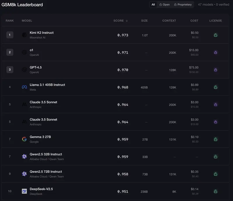
Top 10 Leaderboard

I have a secret passion for LFM2.5-Thinking. It’s tiny 1.2B, it’s fast, it’s a reasoning model, and it’s good. Really good.

My tests are still in progress. All i can do is share some early results. I use the public GSM8k dataset, but with my own benchmarking scripts.

What is the GSM8k benchmark?

Grade School Math 8K, a dataset of 8.5K high-quality linguistically diverse grade school math word problems requiring multi-step reasoning and elementary arithmetic operations.

The Top 10 Leaderboard in 2026, up to 97%. Take note of the massive context size.

Top 10 Leaderboard

And this what “State of the Art” results looked like in 2021, barely 35%.

SOTA GSM8k in 2021

Some early results

Questions: 1319 (test)
Context sizes to test: [1000, 2000, 3000, 4000, 5000, 6000, 7000]
Endpoint: http://192.168.1.110:8000 / lfm2.5-thinking

=== max_tokens=1000 ===
  [200/1319] acc=135/200 (67.5%) rate=3.9q/s
  [400/1319] acc=251/400 (62.8%) rate=4.6q/s
  [600/1319] acc=387/600 (64.5%) rate=5.0q/s
  [800/1319] acc=512/800 (64.0%) rate=5.1q/s
  [1000/1319] acc=640/1000 (64.0%) rate=5.3q/s
  [1200/1319] acc=771/1200 (64.2%) rate=5.3q/s
  Result: 851/1319 (64.5%) @ 5.48q/s

=== max_tokens=2000 ===
  [200/1319] acc=163/200 (81.5%) rate=2.1q/s
  [400/1319] acc=321/400 (80.2%) rate=2.3q/s
  [600/1319] acc=479/600 (79.8%) rate=2.5q/s
  [800/1319] acc=636/800 (79.5%) rate=2.5q/s
  [1000/1319] acc=791/1000 (79.1%) rate=2.5q/s
  [1200/1319] acc=956/1200 (79.7%) rate=2.6q/s
  Result: 1055/1319 (80.0%) @ 2.63q/s

=== max_tokens=3000 ===
  [200/1319] acc=171/200 (85.5%) rate=1.5q/s
  [400/1319] acc=341/400 (85.2%) rate=1.5q/s
  [600/1319] acc=505/600 (84.2%) rate=1.5q/s
  [800/1319] acc=674/800 (84.2%) rate=1.5q/s
  [1000/1319] acc=836/1000 (83.6%) rate=1.5q/s
  [1200/1319] acc=1008/1200 (84.0%) rate=1.5q/s
  Result: 1113/1319 (84.4%) @ 1.57q/s

=== max_tokens=4000 ===
  [200/1319] acc=175/200 (87.5%) rate=1.1q/s
  [400/1319] acc=348/400 (87.0%) rate=1.1q/s
  [600/1319] acc=517/600 (86.2%) rate=1.1q/s
  [800/1319] acc=683/800 (85.4%) rate=1.1q/s
  [1000/1319] acc=852/1000 (85.2%) rate=1.1q/s
  [1200/1319] acc=1033/1200 (86.1%) rate=1.1q/s
  Result: 1139/1319 (86.4%) @ 1.17q/s

=== max_tokens=5000 ===
  [200/1319] acc=176/200 (88.0%) rate=0.8q/s
  [400/1319] acc=350/400 (87.5%) rate=0.9q/s
  [600/1319] acc=523/600 (87.2%) rate=0.9q/s
  [800/1319] acc=687/800 (85.9%) rate=0.9q/s
  [1000/1319] acc=850/1000 (85.0%) rate=0.9q/s
  [1200/1319] acc=1025/1200 (85.4%) rate=0.9q/s
  Result: 1129/1319 (85.6%) @ 0.93q/s

=== max_tokens=6000 ===
  [200/1319] acc=181/200 (90.5%) rate=0.7q/s
  [400/1319] acc=351/400 (87.8%) rate=0.7q/s
  [600/1319] acc=523/600 (87.2%) rate=0.7q/s
  [800/1319] acc=696/800 (87.0%) rate=0.7q/s
  [1000/1319] acc=863/1000 (86.3%) rate=0.7q/s
  [1200/1319] acc=1048/1200 (87.3%) rate=0.7q/s
  Result: 1153/1319 (87.4%) @ 0.73q/s

=== max_tokens=7000 ===
  [200/1319] acc=172/200 (86.0%) rate=0.5q/s
  [400/1319] acc=346/400 (86.5%) rate=0.6q/s
  [600/1319] acc=520/600 (86.7%) rate=0.6q/s
  [800/1319] acc=683/800 (85.4%) rate=0.6q/s
  [1000/1319] acc=853/1000 (85.3%) rate=0.6q/s
  [1200/1319] acc=1034/1200 (86.2%) rate=0.6q/s
  Result: 1137/1319 (86.2%) @ 0.61q/s

=== Summary ===
max_tokens  accuracy   correct   total    rate
      1000     64.5%       851    1319    5.5
      2000     80.0%      1055    1319    2.6
      3000     84.4%      1113    1319    1.6
      4000     86.4%      1139    1319    1.2
      5000     85.6%      1129    1319    0.9
      6000     87.4%      1153    1319    0.7
      7000     86.2%      1137    1319    0.6

LFM2.5 result

About boxed & fallback. The model is requested to put the result in a “boxed” format, but it sometimes fail to do so. I have some “fallback” parsing to try to extract the answer anyway

I’m not running my full suite, therefore there might be some false negatives here (improper parsing, flag correct result as incorrect).

You’ll hear me saying it at lof time on dev.to, i don’t have enough compute power. Yet, it’s a good rough estimate.

TODO

I need to double check the results, i need to check longer context, i need to check another model, i need to test turboquant, and so much more…

I Tested TurboQuant KV Cache Compression on Consumer GPUs. Here’s What Actually Happened.

I spent this weekend testing TurboQuant KV cache compression on my home lab Kubernetes cluster. The paper (ICLR 2026, Google Research) promises up to 4.57x compression of the KV cache with minimal quality loss. That sounded like exactly what I needed. I’m always bumping up against VRAM limits trying to run larger models or longer contexts on consumer hardware.

Here’s what I found: it works, but there are real tradeoffs nobody’s talking about yet.

The Problem: KV Cache Eats Your VRAM

If you’ve run LLMs locally, you know the drill. You load a 32B model that fits in 20GB of VRAM, set the context to 32K, and suddenly you’re at 28GB. The model weights didn’t change. It’s the KV cache growing linearly with context length.

For every token in the context, the model stores key and value vectors for every attention head at every layer. In FP16, that adds up fast. A 32B model at 32K context can burn through 8+ GB of VRAM just for the KV cache.

TurboQuant’s approach is to apply a Walsh-Hadamard Transform (WHT) rotation to KV cache vectors before quantizing them to 3 bits. The rotation “gaussianizes” the distribution, making scalar quantization much more effective. The result is TQ3_0: roughly 3 bits per element instead of 16, for a theoretical 4.57x compression.

My Setup

Hardware: ShadowStack, my home inference server

  • 2x NVIDIA RTX 5060 Ti (16GB GDDR7 each, 32GB total)
  • AMD Ryzen 9 7900X, 64GB DDR5
  • Ubuntu 24.04, MicroK8s

Software: LLMKube, an open-source Kubernetes operator I built for managing llama.cpp inference workloads. It handles model downloads, GPU scheduling, multi-GPU sharding, health probes, and Prometheus metrics through Kubernetes CRDs.

TurboQuant build: I used the animehacker/llama-turboquant fork, which has working CUDA kernels for the WHT-based TQ3_0 type. This is a Stage 1 implementation (no QJL residual correction from the full paper). I built it with Kaniko directly on my cluster targeting SM 86 (Ampere) and SM 120 (Blackwell).

The Wrapper Entrypoint Pattern

LLMKube’s InferenceService CRD doesn’t have a --cache-type flag yet, so I built a custom Docker image with a wrapper entrypoint that injects the TurboQuant flags transparently:

#!/bin/bash
# entrypoint.sh - passes through all LLMKube args, appends TQ flags
TQ_CACHE_TYPE="${TQ_CACHE_TYPE:-tq3_0}"
TQ_ENABLED="${TQ_ENABLED:-true}"

if [ "${TQ_ENABLED}" = "true" ]; then
    exec llama-server "$@" --cache-type-k "${TQ_CACHE_TYPE}" --cache-type-v "${TQ_CACHE_TYPE}"
else
    exec llama-server "$@"
fi

Using exec is important. It makes llama-server PID 1 so Kubernetes health probes and signal handling work correctly.

Benchmark Methodology

Apples-to-apples. Same model weights, same context size, same concurrency. The only variable was the KV cache type (FP16 vs TQ3_0). Flash attention was enabled for all tests.

Throughput test: 5 minutes of sustained load at 4 concurrent requests, 8K context.

Context sweep: Deploy at each context size (4K through 131K), run a 2-minute stress test, record VRAM via nvidia-smi.

Models tested:

  • Llama 3.1 8B (Q5_K_M), small model with lots of headroom
  • Qwen 2.5 14B (Q5_K_M), medium model that fills one GPU
  • Qwen 2.5 32B (Q4_K_M), large model that requires both GPUs

Results: Throughput

This is where TurboQuant hurts.

Model Variant Gen tok/s Prompt tok/s Requests (5min)
Llama 8B FP16 cache 50.0 565.5 771
Llama 8B TQ3_0 cache 8.4 93.4 74
Qwen 14B FP16 cache 28.1 122.0 128
Qwen 14B TQ3_0 cache 5.3 63.4 53
Qwen 32B FP16 cache 14.3 133.3 108
Qwen 32B TQ3_0 cache 5.5 85.5 53

Generation throughput dropped 5-6x across all models. Prompt processing dropped roughly 2-6x depending on model size. This is consistent with what the PR benchmarks showed on CPU, but I expected Blackwell’s tensor cores to help more than they did. The animehacker CUDA kernels were optimized for Ampere (SM 86), not Blackwell (SM 120), so there’s likely performance left on the table.

Results: VRAM Usage

This is where it gets interesting.

Llama 3.1 8B, Context Sweep

Context FP16 VRAM (total) TQ3_0 VRAM (total) Savings
4K 6.4 GB 10.1 GB -58% (worse)
8K 6.9 GB 14.3 GB -107% (worse)
16K 8.0 GB 22.8 GB -185% (worse)
32K 10.1 GB 6.9 GB 31% better
65K 14.3 GB 8.4 GB 41% better
98K 18.5 GB 9.8 GB 47% better
131K 22.7 GB 11.2 GB 51% better

Qwen 2.5 14B, Context Sweep

Context FP16 VRAM (total) TQ3_0 VRAM (total) Savings
4K 11.1 GB 16.7 GB -50% (worse)
8K 11.9 GB 23.0 GB -93% (worse)
16K 13.4 GB 11.0 GB 18% better
32K 16.6 GB 11.8 GB 29% better
65K 22.8 GB 13.7 GB 40% better

Qwen 2.5 32B, Context Sweep

Context FP16 VRAM (total) TQ3_0 VRAM (total) Savings
2K 19.9 GB 23.7 GB -19% (worse)
4K 20.5 GB 27.9 GB -36% (worse)
8K 21.6 GB 19.8 GB 8% better
16K 23.7 GB 20.3 GB 14% better
32K 28.0 GB 21.4 GB 24% better

The Surprise: TQ Uses MORE VRAM at Small Contexts

I wasn’t expecting this. At 4K-16K context, TQ3_0 consistently used more VRAM than the FP16 baseline. Sometimes dramatically more. Llama 8B at 16K context used 22.8 GB with TQ vs 8.0 GB with FP16.

My theory: the WHT rotation machinery has a fixed overhead (lookup tables, rotation matrices, codebooks) that gets allocated regardless of context size. When the KV cache is small, this overhead dwarfs the compression savings. The crossover point where TQ starts winning varies by model:

  • Llama 8B: around 32K context
  • Qwen 14B: around 16K context
  • Qwen 32B: around 8K context

Larger models cross over earlier because their per-token KV cache is larger (more layers, more attention heads), so the compression pays off sooner.

When Is TurboQuant Worth It?

Use TQ3_0 when:

  • You need 32K+ context on consumer GPUs
  • You’re hitting VRAM limits and can’t afford more hardware
  • Throughput isn’t critical (batch processing, RAG with long documents, analysis tasks)
  • You’re running a large model (32B+) where the crossover point is lower

Don’t use TQ3_0 when:

  • Context is under 16K (you’ll actually use more VRAM)
  • You need interactive throughput (the 5x penalty makes chat unusable)
  • You’re on Blackwell and want optimal performance (wait for SM 120-optimized kernels)

The sweet spot in my testing was Qwen 32B at 32K context. Baseline uses 28 GB, which is dangerously close to my 32 GB ceiling. One concurrent request could OOM. TQ drops it to 21.4 GB, leaving over 10 GB of headroom for parallel slots or longer contexts.

What’s Next

The throughput penalty is the main blocker. The animehacker CUDA kernels use a fused MMVQ approach that avoids dequantization during attention, but the WHT butterfly transform still runs 160 integer ops per element in registers. On Blackwell with its new SM architecture, these kernels likely aren’t hitting optimal occupancy.

Things I’m watching:

  • PR #21089 on ggml-org/llama.cpp, the only open upstream PR for TurboQuant (CPU-only for now)
  • Whether ggerganov engages with it. If he requests changes rather than closing, it’ll eventually land.
  • SM 120-optimized CUDA kernels. Blackwell has new instructions that could close the throughput gap.

For LLMKube, I’m planning to add cacheTypeK and cacheTypeV fields to the InferenceService CRD so users can configure this without the wrapper entrypoint hack. Also an extraArgs escape hatch for any llama.cpp flag we don’t have a typed field for yet.

Try It Yourself

All the benchmarking infrastructure is in the LLMKube repo. The operator is open source (Apache 2.0) and handles the full lifecycle: model downloads, GPU scheduling, multi-GPU sharding, health probes, and Prometheus metrics. If you have a GPU cluster and want to test TurboQuant:

  1. Build the custom image from animehacker/llama-turboquant with -DGGML_CUDA=ON
  2. Set spec.image on your InferenceService to point at it
  3. The wrapper entrypoint handles the rest

If you run these benchmarks on different hardware (A100, RTX 3090, etc.), I’d love to see the numbers. Drop a comment or find me on the LLMKube Discord.

Benchmarks run on 2026-03-30 on ShadowStack (2x RTX 5060 Ti, 32GB VRAM, Blackwell SM 12.0, CUDA 13.0).

Serverless applications on AWS with Lambda using Java 25, API Gateway and DynamoDB – Part 3 Introducing Lambda SnapStart

Introduction

In part 1, we introduced our sample application. In part 2, we measured the performance (cold and warm start times) of the Lambda function without any optimizations. We observed quite a large cold start time. In this article, we’ll introduce AWS Lambda SnapStart as one of the approaches to reducing the cold start times of the Lambda function. We’ll also provide the cold and warm start measurements of the sample application when the SnapStart is enabled for the Lambda function.

AWS Lambda SnapStart

As we saw in part 2, without any optimizations, Lambda performance measurements showed quite high values, especially for the cold start times. The article Understanding the Lambda execution environment lifecycle provides a good overview of this topic. Lambda SnapStart is one of the optimization approaches to reduce the cold start times.

Lambda SnapStart can provide a start time of a Lambda function of less than one second. SnapStart simplifies the development of responsive and scalable applications without provisioning resources or implementing complex performance optimizations.

The largest portion of startup latency (often referred to as cold start time) is the time Lambda spends initializing the function, which includes loading the function code, starting the runtime, and initializing the function code. With SnapStart, Lambda initializes our function when we publish a function version. Lambda takes a Firecracker microVM snapshot of the memory and disk state of the initialized execution environment. Then it encrypts the snapshot and intelligently caches it to optimize retrieval latency.

To ensure reliability, Lambda manages multiple copies of each snapshot. Lambda automatically patches snapshots and their copies with the latest runtime and security updates. When we invoke the function version, Lambda restores a new execution environment from the cached snapshot, instead of initializing it from scratch, which improves startup latency. You can find more information about the Lambda SnapStart in the article Reducing Java cold starts on AWS Lambda functions with SnapStart. You can also read about the internals of the SnapStart in the article Under the hood: how AWS Lambda SnapStart optimizes function startup latency. I have published the whole series about Lambda SnapStart for Java applications.

Measurements of cold and warm start times of the Lambda function of the sample application

We’ll reuse the sample application from part 1 and do exactly the same performance measurement as we described in part 2. We’ll measure the performance of the GetProductByIdJava25WithDynamoDB Lambda function mapped to the GetProductByIdHandler. We will trigger it by invoking curl -H “X-API-Key: a6ZbcDefQW12BN56WEVDDB25” https://{$API_GATEWAY_URL}/prod/products/1.

One important aspect is that we instantiate Jackson ObjectMapper and ProductDao directly in the static initializer block of the GetProductByIdHandler Lambda function:

public class GetProductByIdHandler
        implements RequestHandler<APIGatewayProxyRequestEvent, APIGatewayProxyResponseEvent> {

private static final ObjectMapper objectMapper = new ObjectMapper();
private static final ProductDao productDao= new ProductDao();
...

When you create an ObjectMapper for the first time, it initializes a lot of other classes. As a part of this process, it instantiates a lot of singletons. It takes, depending on the hardware, more than a hundred milliseconds. If you create the second ObjectMapper in the same Java process, it takes only 1 millisecond because all the singletons are already there.  By moving the ObjectMapper instantiation to the static initializer block of the Lambda function, we decrease the cold start time. The reason for that is that this initialized object becomes a part of the SnapStart snapshot.

The same is true for ProductDao, especially taking into account that we directly create the instance of the DynamoDbClient there:

public class ProductDao {

private static final DynamoDbClient dynamoDbClient = DynamoDbClient.builder()
  .credentialsProvider(DefaultCredentialsProvider.builder().build())
  .region(Region.of(REGION.toLowerCase()))
  .overrideConfiguration(ClientOverrideConfiguration.builder().build())
  .build();
....

This, in turn, loads a lot of classes, which also become a part of the SnapStart snapshot.

Also, please make sure that we have enabled Lambda SnapStart in template.yaml as shown below:

Globals:
  Function:
    Handler: 
    SnapStart:
      ApplyOn: PublishedVersions 
    ....
    Environment:
      Variables:
        JAVA_TOOL_OPTIONS: "-XX:+TieredCompilation -XX:TieredStopAtLevel=1"

Please note that I measured only the performance of the Lambda function. On top of that comes also the latency of the trigger – in our case, the API Gateway REST API.

Please also note the effect of the Lambda SnapStart snapshot tiered cache. This means that in the case of SnapStart activation, we get the largest cold starts during the first measurements. Due to the tiered cache, the subsequent cold starts will have lower values. For more details about the technical implementation of AWS SnapStart and its tiered cache, I refer you to the presentation by Mike Danilov: “AWS Lambda Under the Hood” and already mentioned article Under the hood: how AWS Lambda SnapStart optimizes function startup latency. Therefore, I will present the Lambda performance measurements with SnapStart being activated for all approx. 100 cold start times (labelled as all in the table), but also for the last approx. 70 (labelled as last 70 in the table), so that the effect of the snapshot tiered cache becomes visible to you. Depending on how often the respective Lambda function is updated and thus some layers of the cache are invalidated, a Lambda function can experience thousands or tens of thousands of cold starts during its life cycle, so that the first longer-lasting cold starts no longer carry much weight.

To show the impact of the SnapStart, we’ll also present the Lambda performance measurements without SnapStart being activated from part 2.

I did the measurements with java:25.v19 Amazon Corretto version, and the deployed artifact size of this application was 13.796 KB.

Cold (c) and warm (w) start time with -XX:+TieredCompilation -XX:TieredStopAtLevel=1 compilation in ms:

Approach c p50 c p75 c p90 c p99 c p99.9 c max w p50 w p75 w p90 w p99 w p99.9 w max
No SnapStart enabled 3800 3967 4183 4411 4495 4499 5.55 6.15 7.00 12.18 56.37 4000
SnapStart enabled but no priming applied, all 2294 2366 3530 3547 3548 3551 5.68 6.30 7.33 13.43 44.74 2923
SnapStart enabled but no priming applied, last 70 2247 2324 2389 2637 2637 2637 5.68 6.35 7.39 13.65 44.03 2051

Conclusion

In this article of the series, we introduced AWS Lambda SnapStart as one of the approaches to reduce the cold start times of the Lambda function. We observed that by enabling the SnapStart on the Lambda function, the cold start time goes down. It’s especially noticeable when looking at the “last 70” measurements with the snapshot tiered cache effect. But still, the cold start remains quite high. In the next article, we’ll explore the first Lambda SnapStart priming technique. I call it the database (in our case, DynamoDB) request priming. The goal of applying priming is to preload and preinitialize as much as possible in the SnapStart snapshot during the deployment phase. With that, all those things will already be available directly after the SnapStart snapshot restore.

Please also watch out for another series where I use a relational serverless Amazon Aurora DSQL database and additionally the Hibernate ORM framework instead of DynamoDB to do the same Lambda performance measurements.

If you like my content, please follow me on GitHub and give my repositories a star!

Please also check out my website for more technical content and upcoming public speaking activities.

How I Designed a Real-Time Dashboard Using Kafka, Socket.IO, and a BFF

GitHub logo

A practical breakdown of the architecture decisions, trade-offs, and frontend/backend boundaries behind Flux — an event-driven real-time dashboard platform I built.

When I started building Flux, I didn’t want to build just another dashboard.

I wanted to build something that actually felt like a real-time system.

  • Not a frontend that keeps polling every few seconds.
  • Not a UI that directly calls five different APIs.
  • Not a project where everything works only when the happy path works.

I wanted something closer to how production systems are usually designed:

  • multiple data domains
  • asynchronous communication
  • real-time delivery
  • graceful degradation
  • and a frontend that stays simple even when the backend gets more complex

So this post is a breakdown of how I designed the architecture for Flux — and more importantly, why I made the decisions I made.

What Flux actually is

Flux is a real-time dashboard that streams and displays:

  • Weather
  • News
  • Stocks
  • Crypto

At first glance, it looks like a frontend-heavy project.

But the interesting part is actually the backend architecture.

Because the real problem wasn’t:

“How do I render cards on a dashboard?”

The real problem was:

“How do I design a system that can ingest, process, and push multiple real-time data streams to clients cleanly?”

That changed everything.

The first architecture I didn’t want

The most obvious way to build this would have been something like this:

Frontend
 ├── calls weather API
 ├── calls news API
 ├── calls stocks API
 └── calls crypto API

This works for a small demo.

But I expected that approach to become painful pretty quickly.

Why I avoided that approach

Because the frontend would slowly become responsible for things it should not own:

  • request orchestration
  • retries
  • service-specific logic
  • failure handling
  • data normalization
  • caching decisions
  • reconnect behavior

That’s how “simple dashboards” become messy.

And honestly, this was one of the main design lines I kept repeating to myself while building this:

I wanted the frontend to stay thin and focused.

Meaning:

  • render data
  • send user intent
  • keep a real-time connection alive

That’s it.

The architecture I settled on

I ended up designing Flux around 3 main layers:

Frontend (Web UI)
 │
 ▼
BFF (Socket.IO + Cache + Kafka coordination)
 │
 ▼
Domain Services (Kafka-based)

This became the core mental model of the whole project.

Each layer has one job.

And once I locked that in, the rest of the system became much easier to reason about.

1) Frontend: thin, reactive, and intentionally limited

The frontend in Flux is intentionally thin and focused.

That was a design choice, not a shortcut.

Its job is to:

  • open a persistent Socket.IO connection
  • send user context (like location)
  • subscribe to real-time updates
  • render whatever arrives

Its job is not to:

  • talk to Kafka
  • call backend services directly
  • aggregate data
  • implement retry policies
  • decide caching behavior

That separation made the frontend much cleaner.

Why this mattered

Because when frontend code starts knowing too much about backend infrastructure, everything becomes harder:

  • harder to debug
  • harder to test
  • harder to scale
  • harder to change later

So in Flux, the frontend only talks to one thing:

the BFF

That one decision removed a lot of future complexity.

2) Why I used a BFF instead of exposing services directly

This was probably the most important architecture decision in the whole project.

I introduced a Backend-for-Frontend (BFF) layer between the UI and the backend services.

What the BFF does

The BFF is responsible for:

  • maintaining client Socket.IO connections
  • receiving events from backend services
  • hydrating reconnecting clients quickly
  • deciding what data to fan out to which users
  • acting as the real-time gateway of the system

So instead of this:

Frontend → many services

I made it:

Frontend → BFF → services

On paper that sounds small.

In practice, it changed a lot.

Why I liked this model

Because the frontend now has:

  • one connection model
  • one integration boundary
  • one real-time contract

And the backend can evolve without breaking the UI every time.

That gave me a much better separation between:

  • presentation concerns
  • system concerns

Which is exactly what I wanted from the start.

3) Why I used Kafka in the middle

Once I knew I wanted multiple real-time domains, I also knew I didn’t want everything tightly coupled.

If weather updates, crypto updates, stock updates, and news updates all depend directly on each other — or on one giant central service — that becomes painful fast.

So I used Kafka as the backbone.

What Kafka gave me

Kafka helped me design the system around events, not direct service-to-service coupling.

That gave me a few nice properties:

  • services can evolve independently
  • producers and consumers don’t need to know too much about each other
  • scaling one domain doesn’t force scaling everything
  • the architecture feels much closer to real production systems

That was important to me.

Because I didn’t want Flux to be a project optimized more for presentation than for system trade-offs.

I wanted it to feel like something that was designed with actual backend trade-offs in mind.

4) Why I chose Socket.IO for real-time delivery

For the client-facing real-time layer, I chose Socket.IO.

And yes — I know raw WebSockets are often the more low-level answer on paper.

But for this project, I cared more about reliability and developer ergonomics than sounding low-level.

Why Socket.IO made sense here

It gave me:

  • automatic reconnection
  • fallback transport support
  • room-based fan-out
  • simpler event semantics
  • less boilerplate for real-time client communication

That mattered because Flux is not just:

“send one stream to one client”

It’s a multi-stream dashboard with different categories of data and different update patterns.

So having a stable, practical abstraction here was worth it.

Sometimes “more production-realistic” is not about choosing the lowest-level primitive.

Sometimes it’s about choosing the thing you can operate more reliably.

5) The problem I ran into: reconnects and hydration

This is where the architecture got more interesting.

Real-time apps are not just about live streaming.

They’re also about:

“What happens when a user reconnects?”

That question forced me to think beyond just pushing events.

Because if a user refreshes the page or reconnects after a network blip, I don’t want them staring at an empty dashboard waiting for all streams to naturally update again.

That creates a poor reconnect experience.

So I split the system mentally into two kinds of data:

A) Snapshot data

Data that should be shown immediately on reconnect

Examples:

  • top news
  • weather snapshot
  • top crypto coins
  • stock summaries

B) Stream data

Data that should continue flowing live

Examples:

  • ticker updates
  • incremental changes
  • fast-moving live events

That separation ended up being very useful.

Because it let me design hydration and streaming differently instead of pretending all real-time data behaves the same way.

And honestly, that was one of the cleanest architecture decisions in the project.

6) Why I added cache, but made it optional

Once I started thinking about reconnect hydration, cache became the obvious next step.

But I also didn’t want to build a system that completely dies if cache is unavailable.

So I used Valkey (open-source Redis fork) as an optional accelerator, not as a hard dependency.

That distinction mattered a lot.

Why “optional cache” was important

Cache is amazing for:

  • fast reconnect hydration
  • reducing repeated work
  • serving recent snapshot data quickly

But I didn’t want Flux to become:

“works only if every dependency is healthy”

So I designed it with this mindset:

  • if cache is available → great, faster experience
  • if cache is unavailable → system should still keep working

That’s a small detail, but it changes how resilient the system feels.

And personally, I’ve started appreciating this design style a lot more:

Acceleration should not become fragility.

7) One of the subtle problems: selective fan-out

Once I had a BFF pushing real-time data, I ran into another question:

“Should every client receive every event?”

In practice, the answer is no.

That would:

  • waste bandwidth
  • add unnecessary frontend filtering
  • generally be inefficient

So I used Socket.IO rooms to scope event delivery.

That meant I could think in terms like:

  • weather by city
  • global news stream
  • crypto stream
  • stock stream

This helped keep the fan-out more intentional instead of just:

“broadcast everything and let the client figure it out”

That’s one of those things that sounds small when you say it in one sentence, but it makes the architecture much cleaner.

8) One frontend decision I’m glad I didn’t stay stubborn about

Initially, I was trying to keep the frontend very clean:

  • hooks handle data and subscriptions
  • components just render UI

And for the most part, that worked well.

Each domain had its own hook:

  • weather
  • news
  • stocks
  • crypto

So the general rule was simple:

Hooks deal with real-time logic. Components stay simple.

That kept things pretty clean.

But then I ran into a small UX problem

In the Crypto card, I had two tabs:

  • Top Movers
  • Live Ticker

And every time I switched between them, I didn’t like what I was seeing.

Some data in the Crypto card would reload again, and state didn’t feel stable across tab switches.

The UI didn’t feel as smooth as I wanted.

Nothing was actually broken.

It just didn’t feel good.

And I’ve started trusting that feeling more while building projects.

Because a lot of times, architecture looks clean in code but feels annoying in the actual product.

So this is where I bent my own rule a bit

Instead of forcing everything through local hook state, I used Redux selectively for the crypto section.

Not across the whole app.

Just where it actually helped.

Mainly to keep things like:

  • ticker data
  • top coins data
  • price-related state

stable across tab switches.

The pattern that felt right was:

  • hooks handle subscriptions and incoming socket events
  • Redux keeps shared UI state stable where needed
  • components just read and render

That ended up feeling much better.

Why I’m glad I did this

Because this was one of those cases where:

being too “architecturally pure” would have made the user experience worse.

And honestly, I’d rather have a slightly more practical architecture than a “perfectly clean” one that adds unnecessary friction to the user experience.

That small change made the Crypto card feel way smoother.

And I think that’s a useful reminder in general:

Sometimes the right architecture decision is just the one that makes the product feel better.

9) Failure isolation was not an afterthought

One thing I really wanted in Flux was this:

If one stream fails, the dashboard should still feel alive.

So I designed the UI and backend with failure isolation in mind.

Meaning:

  • if weather is delayed → crypto still updates
  • if news fails → stocks still render
  • if one service lags → the whole app shouldn’t feel dead

That sounds like a UX decision, but it’s actually an architecture decision too.

Because if your system shape forces everything to depend on everything else, then partial failure becomes full failure.

And I wanted to avoid that.

A real-time system should degrade, not collapse.

10) I intentionally did not chase “perfect distributed systems purity”

This was a very conscious choice.

Because once you start building event-driven systems, it’s very easy to go down the rabbit hole of:

  • exactly-once everything
  • over-engineered delivery guarantees
  • too many abstractions too early
  • adding architectural complexity that doesn’t meaningfully improve the system

I tried hard not to do that.

So Flux is opinionated in a practical way.

I optimized for:

  • clarity
  • resilience
  • clean boundaries
  • realistic trade-offs

Not unnecessary complexity.

That was important to me because I wanted this project to reflect how I actually think as an engineer:

I like systems that are thoughtful, not just complicated.

Final architecture summary

If I had to describe Flux’s architecture in one sentence, I’d say:

It’s a real-time dashboard designed like a small event-driven platform, not like a frontend project with extra backend code attached.

That’s the difference I cared about.

The main ideas behind the design were:

  • keep the frontend thin
  • centralize real-time delivery in a BFF
  • use Kafka for loose coupling
  • use Socket.IO for practical real-time delivery
  • separate snapshot hydration from live streams
  • use cache as an accelerator, not a crutch
  • isolate failures so the whole app doesn’t feel broken

And honestly, designing those boundaries was way more interesting than building the UI itself.

What I learned from building this

If I had to compress the biggest lesson into one line:

Most architecture problems become easier once each layer has one clear responsibility.

A lot of messy systems are messy because responsibilities are blurry.

Flux became much easier to build once I stopped asking:

“How do I make everything talk to everything?”

…and started asking:

“What is each layer allowed to know?”

That single shift made the architecture cleaner.

If you’re building a real-time dashboard too

A few things I’d strongly recommend:

  • Don’t let the frontend talk to too many things directly.
  • Decide early what is snapshot data vs stream data.
  • Design for reconnects, not just the initial page load.
  • Think about partial failure early.
  • Keep boundaries boring and explicit.

That alone will save you a lot of pain later.

Final thoughts

If you’ve built something similar — or if you would have designed this differently — I’d genuinely love to hear your approach.

I always find architecture discussions more useful when they’re about trade-offs as well as best practices.

GitHub logo

kaustubh-26
/
flux-platform

An event-driven real-time data platform

Flux Platform

Flux — An event-driven real-time data platform

Build
Tests
Deploy
License

Live Demo: https://flux.kaustubhalandkar.workers.dev

A production-style, event-driven real-time data platform showcasing modern Kafka-based streaming, WebSocket fan-out, and a clean Backend-for-Frontend (BFF) architecture.

This repository is intentionally built as a portfolio-grade, open-source system that mirrors how real-world, streaming data platforms are designed, operated, and documented.

🖥️ Live Dashboard Preview

📱 Mobile View

✨ What This Project Demonstrates

  • Event-driven microservices using Kafka
  • A resilient BFF layer for real-time fan-out
  • Socket.IO–based client streaming
  • Cache-accelerated hydration with graceful degradation
  • Idempotency & deduplication patterns
  • Structured logging & observability
  • Self-healing Kafka connectivity
  • Clean, scalable monorepo organization

The project emphasizes real-world system design concerns such as event-driven communication, failure handling, and scalability.

🧠 High-Level Architecture

┌──────────────────────┐
│        Client        │
│  Browser / Mobile    │
└─────────▲────────────┘
          │ Socket.IO (real-time)
┌─────────┴──────────────┐
│   Backend-for-Frontend │
│          (BFF)         │
│  - Socket.IO Server    │
│  - Kafka Producer      │

…